Torsion Springs
Design of a Torsion Spring
The objective is to determine the wire diameter and the coil dimensions of a torsion spring for a given torsional moment.
The dimensioning is done according the standard DIN EN 13906-3. The user is guided through the calculation operation by a wizard sheet.
Design Specifications
On opening of the wizard sheet, a wizard page with a list of spring wire grades is beeing displayed. A spring wire grade file
is supplied with the application. The file contains wire grades according the standards EN 10270-1, 2 and 3, EN 10089,
Copper-tin alloys EN12166. The user can update the spring wire grades file with data of the wires he will use.
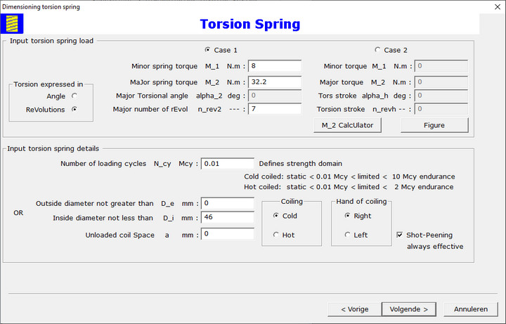
Input design specifications with following wizard page:

There is a selection to be made for torsional deflection expressed in angle degrees or in revolutions. Two cases are provided for input of the spring load.
Case 1: input minor torsional moment M1, major torsional moment M2 and major torsional angle α2
or number of revolutions nrev2.
Case 2: input minor torsional moment M1, major torsional moment M2 and stroke angle αh
or stroke revolutions nrevh.
Input of the number of loading cycles Ncy, the lower bound for the coil inside diamter Di, the winding space a.
Selection with radio buttons for cold or hot coiling, hand of coiling and checkbox if shot peening will be applied.
The application calculates the required wire diameter d. The user decides the wire diameter he's gonna to use.
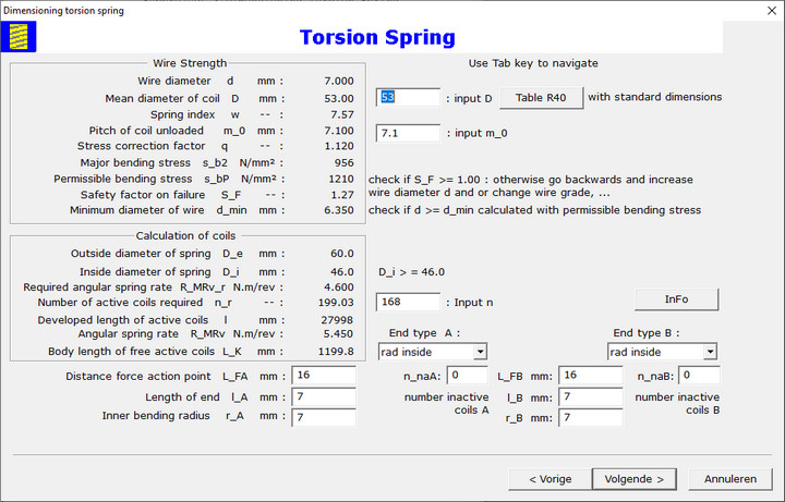
Then the wizard page under neath is displayed on the screen with the calculation results:

The user has to decide about the coil mean diamter D,
the free state pitch m0 and the number of active coils n. The input is to be completed with the data for the legs
at the spring ends A and B.
The calculation involves geometry, the spring rate and the strength. The calculation results are displayed in the next wizard page. Go to the next
web page to see the spring diagram.