Calculation of Stresses
In the extreme vertices of a cross section, the bending stress is maximal, while the torsional shear and transverse shear
are 0 or negligible small.
In the mid points of outer flanges and webs, the bending stresses are 0 or small, while the torsion shear and
the transverse shear stresses are maximal.
Hence the vertex and mid points are examined separately.
Calculation of stress in four extreme vertex points:
bending stresses σz1,2,3,4 and normal stress σzn [N/mm²], comparison stress σcomp
and the safety factor on failure SF.
Calculation of stress in the outer mid points:
bending stesses σz1,2,3,4 and normal stress σzn [N/mm²], torsional stress
τt [N/mm²], shear stresses τsy and τsx, comparison stress σcomp
and safety factor on failure SF.
Draw up of comparison stress diagram for both cases.
Calculation of Deflections
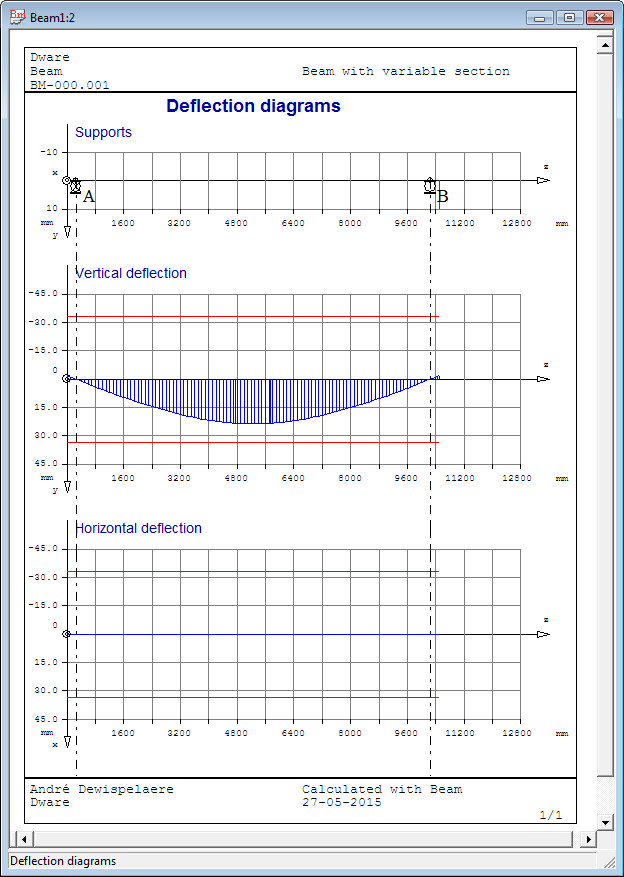
The lateral deflections are calculated and presented in a table. Vertical deflection y and horizontal deflection x and twist angle φ.
Example of vertical and horizontal deflection diagram:

Calculation of natural frequency
The natural or 'eigen' frequency is determined for the first bending mode.
The own weight of the beam and the distributed load (converted to a mass load) is taken into account for the mass-spring model.
The distributed load is considered as a mass rigidly connected to the beam.
Dimensioning Problem
Input of permissible stress σP [N/mm²] and the permissible deflection fP [mm].
Selection of a cross section with the Cross Section Switch dialog. See verification problem.
For a welded plate beam, the minimum required cross section is determined for the I - or box section to respect
the stress - and deflection limits. In the dialog box the required input is displayed: b/h width/depth ratio,
the flange thickness t and the web thickness s. The application iterates a calculation loop until
the cross section respects the stress and deflection limits. Calculation results are displayed in a table: z, h, b, and b/h.
The results table can be printed.